- Announcements
- BBQ and Food
- Cars
- Computing
- Cool Stuff
- Current Events
- Electric Vehicles
- Electronics
- Energy
- Flashahaulism
- Funny
- Government
- Hints and Tips
- History
- HVAC
- Induction heating
- Internet
- Lighting
- Misc
- Neon and other lighting
- Nuclear
- Personal
- Pets
- Philosophy
- Photography
- Power Generation
- Product Reviews
- Projects
- Q and A
- RV/Camping
- Science
- Tellico
Categories
Blogroll
 Print This Post
Dissection of a Furnace Fan Motor
PermaLinkor Why There is so Much BS on the Net.
In this post I’m going to take you through a guided tour of the common everyday fan motor that drives the fan in just about every domestic air conditioner, furnace or heat pump. At the same time I’m going to demonstrate why there is so much utter rubbish on the net, especially in forums and Usenet newsgroups where people can hide behind nyms and other anonymous mechanisms.
Hidden behind a nym, a person can say just about anything, regardless of how silly, and unless challenged, it will become gospel. The problem in fighting this problem is the “10:1” factor. That is, for every minute some anonymous BS’er spends spewing his garbage, it takes about 10 minutes to research and gather evidence to refute it. Probably the worst example is Wikipedia but then that’s the topic of another article.
Hang in there with me, folks, as this one is going to be long but hopefully interesting.
This all started a few days ago when someone in alt.energy.homepower asked how he could slow down his furnace fan to reduce the noise and power consumption. I listed several techniques, including using a phase angle SCR controller (light dimmer), series resistance or even some series reactance (a capacitor or inductor in series with the motor.) I also recommended that the better option would be a slower, multi-speed motor.
Fairly standard information transaction, right? A guy asks a simple question and I, someone who has worked with HVAC and electric motors, both on the engineering and service level for most of my life, gave a straight-forward answer. Unfortunately, nothing’s simple on the net.
Someone who hides behind the nym of “Daestrom” stuck his head up out of the ooze and flamed my answer. This is how it started.
“Using a dimmer on anything but the smallest of induction motors is asking for trouble. Running induction motors on less than their rated voltage is a pretty sure-fire way to burn them out. Same with putting a cap in series with the line, it does the same thing and reduces the terminal voltage to the motor.”
I have kind of a code regarding answering questions on the net. I don’t answer in the assertive voice unless I have actual experience and first-hand knowledge. Otherwise, I hedge my advice with words like “it should work” or “it probably will”. In this case, slowing furnace fans with light dimmers is something that I’ve done many times. I like to grab the fan out of an old air handler that has been removed from service, install a motor-grade SCR controller and then use it for air movement in my shop and elsewhere. We have several of these at the electric motor shop where I moonlight. It works fine.
Having some anonymous twit (who has variously claimed to be anything from a nuclear sub commander to a commercial nuclear plant reactor operator to an engineer) dispute advice based on long personal experience was, to say the least, annoying. This little exchange took place
> ME:
> There ARE some single phase motors that simply cannot
> be slowed with a phase angle controller but they aren’t
> used in furnace blowers and so there is no need to muddy
> the water with those details.HIM:
Induction motors of any size can be burned out when run on lower than rated voltage. It’s a simple fact. Ever have to replace a ‘fridge compressor because of low line voltage? How about the ‘acrid odor’ from a burned out blower motor?
This is a familiar tactic, try to divert attention away from your mistake by taking the conversation off on a tangent. Refrigerator compressor, indeed!
Tired of this, I bet him $1000 that I could slow a furnace fan to any useful speed using a light dimmer and not harm it. “Daestrom” performed as usual, “crawfishing”* loudly while trying to draw some of his buddies from elsewhere into the discussion. As if hard science matters are resolved by concensus. Sounds like the Flat Earth Society at work to me.
*Crawfishing is a term we use here in the South to describe a coward who duplicates the actions of a crawfish. When challenged, a crawfish uses his tail to scoot away backward while waving his pincers vigorously to distract the predator.
Part of his attempt at diverting attention was this:
Temperature rise in the motor is not something you can measure with a thermocouple attached on the outside, or even on the winding. It’s internal to the slot where the heat has the hardest time being conducted away from the source. Large motors often have temperature detectors embedded in the winding during manufacture. Motors that are ‘internally protected’ often have the protective device embedded as well. You going to take your motor and unwind it to put a detector in the proper place? Better not, you probably wouldn’t know how to re-wind it again.
“Large motors”? “Thermocouple in the slot?” WTF? We’re talking about a friggin’ fractional HP home furnace motor, fer Christ’s sake. And of course, the gratuitous insult.
At this point another anonymous “expert” who calls himself “Cydrome Leader” (sounds like a case of arrested maturity to me) pops in with this:
> ME:
> But we’re not talking about large motors are we? The notion
> of a thermal protection thermostat being embedded in the
> tiny slots of a furnace fan blower is hilarious. The
> “proper place” for the thermal sensor is strapped to the
> outside of the windings’ end turns. Or to the end bell.HIM
It’s really not.plenty of small blower type motors have a thermal protector wedged into the slots for the windings.
Tear some motors apart and take a look. The resettable ones are usually rectangular cross section metal tubes wrapped in a plastic or paper sleeve, with leads coming out one side.
Then another fellow who, to his credit, uses his real name but signs himself “PE” chimes in with:
To be fair to NJ, you could install a thermal protector on the ends of the windings, with the knowledge that it would see temperatures perhaps 10-15c cooler than the maxcimum, and with an appropriate setting. However, I have not seen them there very often. On the other hand, the earlier discussion was about measuring the winding temperature during operation, and this should be done in the slot to get the worst case. Another method often used is rise of esistance, which gives an avarage temperature. Again, you would
need to apply a factor to get the maximum temp.
—
Benjamin D Miller, PE
www.bmillerengineering.com
Now “PE” stands for “Professional Engineer”, someone who took a fairly meaningless test early in his career and in return is licensed by the state. (That is, the state has someone to blame when the project screws up.) He is also legally liable for his opinions, expressly so when he “stamps” a document with his name and implicitly so otherwise. Which is why I decided not to acquire the license after passing that test.
PEs (we who have to deal with ’em call ’em “paralyzed engineers” and, well, some other “P” words that aren’t used in polite company. They’re also sometimes known as “NO-gineers” because if one always say NO, it’s hard to be blamed for anything.) tend to be so fearful of being held liable for their advice that they write wishy-washy meaningless stuff like in that paragraph above. He used a lot of words but didn’t cite a single fact that one could hang his hat on or verify.
At this point, the Obfuscation Brigade had worked themselves into a corner (with some nudging from me, of course) to where it became time for some show’n’tell fun.
Show ‘n Tell
Tonight I decided to spend a little time, go into my shop and dissect a squirrel cage blower and its motor, take some photos and write this article. Hang on. This’ll be fun. As a reminder, one anonymous poster claimed that thermal protection on these motors is embedded in the stator slot and our resident PE claims that external sensors aren’t common. I’m not sure where else he could be suggesting unless he’s on the “in the slot” bandwagon. On to some photos.

In this first photo we see the fan with major parts identified. This fan uses a simple plain sleeve bearing 3 speed permanent capacitor run squirrel cage induction motor. Whew! What a mouthfull. It’s a general purpose replacement made by GE. With all these photos, click on the image for a larger version.
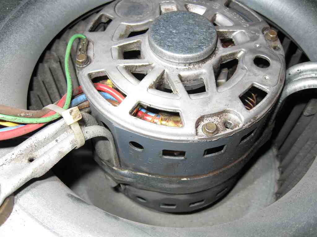
In this photo we observe the motor itself. Notice how it is set inside the squirrel cage blower. This is so that it can be cooled by the fairly high velocity air entering the blower. This is called “air over” cooling. This type of motor is generally unsuitable for other uses, as it lacks a cooling fan and will overheat.
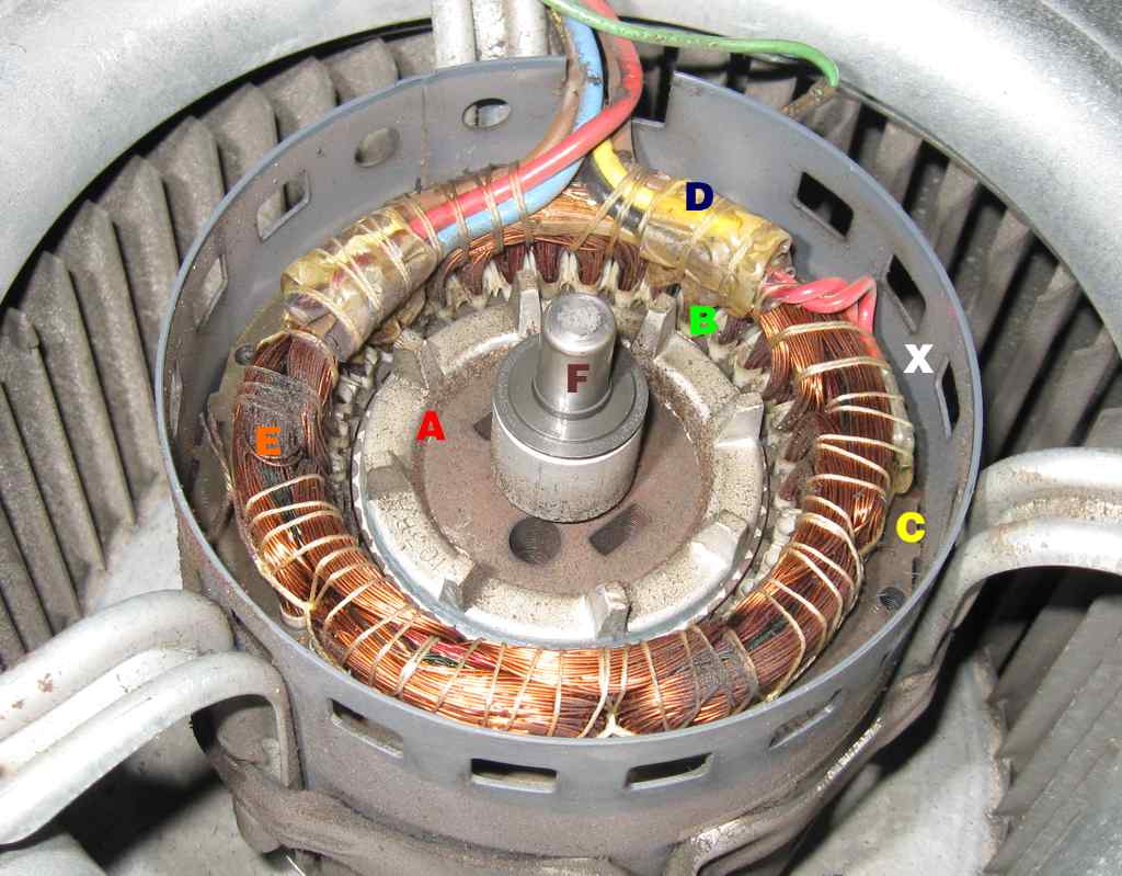
This photo shows the motor with the end bell removed. The various parts are labeled:
A – Is the Squirrel Cage rotor. It is so named because if all the iron were stripped away, the electrical conductors would look like a squirrel cage, the kind of cage that a hamster or rat runs in.
B – Are the slots in the stator where the windings are placed. Notice how full the slots are. Try to imagine anything else fitting in there.
C – is the stator iron, the part that holds the windings and conducts the magnetic field to the rotor
D – are the connections between the incoming heavy wire and the fine magnetic wire that the stator is wound with. You will notice in this photo and ones to follow that there are several sizes and colors of wire used. This is because the slower speeds don’t requires as much current handling capability as the higher speed windings do and so can be would from smaller wire.
E – is the stator windings. These generate the rotating magnetic field that acts on the rotor (A) and makes it turn. These winding are also what overheat when the motor is overloaded.
F – is the end of the shaft that serves as the rotating part of the plain bronze bearing. This is the cheap type of bearing that is most common. More expensive, longer lived motors use ball bearings.
X – Keep an eye on that l’il booger!

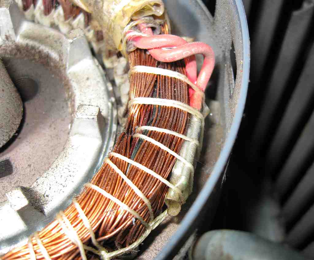
This photo is a close-up of the rotor, stator, the slots, the windings and the incoming wiring. You can see how tightly the slots are filled with windings. Each slot is insulated with “slot paper” (usually Kevlar these days) that protects the fragile copper (or sometimes aluminum) wires from the slots. You can also see how the “end turns” of the windings are laced tightly with lacing twine. This holds the windings in place and keep them from vibrating, creating hum. This appears to be waxed nylon twine. In our motor shop we usually use kevlar twine which is vastly stronger, more heat resistant and more expensive.
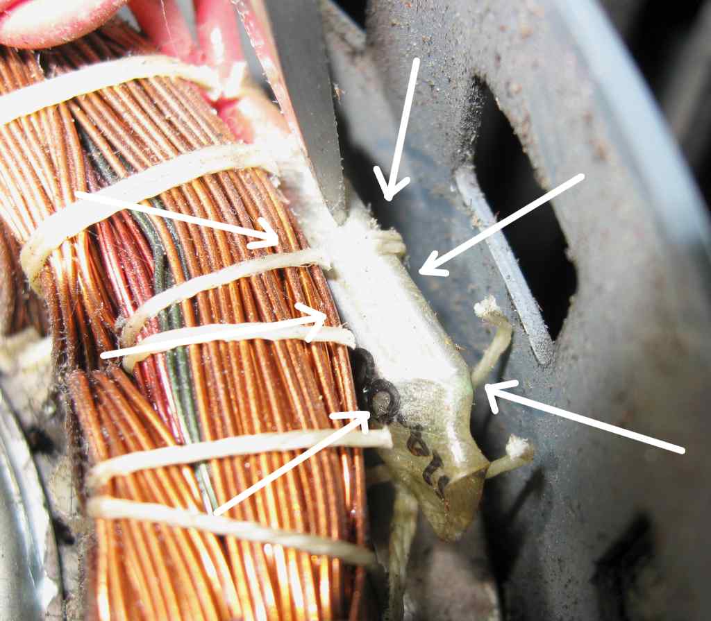
Remember that item labeled “X” above? Here’s a closeup. Yep, it’s the thermal overload device (thermostat), laced right into the “end turns” just as I described in my Usenet post. See why I considered the concept of that thing being crammed into a slot so hilarious?
This device senses the temperature of the winding and opens when the winding gets too hot, turning off the motor. After the motor cools, the thermostat resets and the motor restarts. If the bearings are worn so that the rotor drags the stator or the run capacitor is bad or the fan blade rotation is blocked, this action repeats indefinitely.
Hopefully somone notices that there is no heat or AC and calls a service man. If not, eventually the thermosat’s contacts weld shut and “all the blue smoke leaks out of the motor”. That is why one should pay attention to any change in the operation or sound of his HVAC unit.
In this photo I have put my motor’s life on the line by cutting the lacing twine (not really, but it sounds dramatic) and I’m holding the thermostat out of its pocket in the winding with a knife blade. As you can see, this is a fairly large device. It fits into a well pressed into the ‘end turns” during the manufacture of the motor.
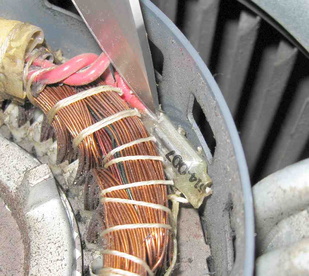
In this view I have lifted the thermostat out even farther from its pocket so that you can get an even better idea of its size. It fits rather deeply into the pressed-in pocket in the windings. It is in intimate thermal contact with the winding.
I think that these photos resolve the question of where the thermal overload is located on an HVAC fan motor – and whose posting was correct.
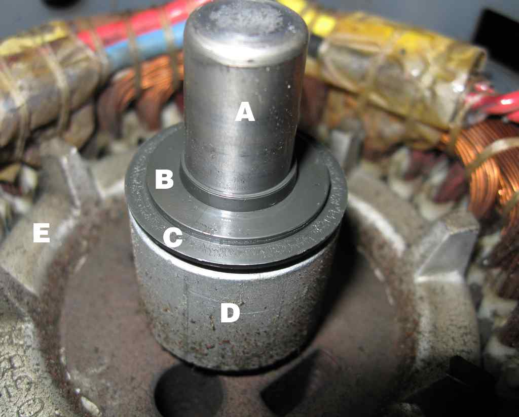
While we’re at it, let’s make this an educational moment and identify the parts of the plain bearing.
A – the shaft and journal. This part is polished so that it floats on a film of oil when running
B- Thrust bearing – absorbs any axial thrust that may be generated during operation. This motor is designed for the shaft to be operated horizontally. For vertically-oriented fan motors, this thrust bearing is much more substantial.
C – Labyrith seal/grease slinger/dust seal. This fits close up against the bearing housing in the end bell to keep dust and dirt out and the lubricant (mostly) in.
D – Spacer Tube. This sets up the proper axial clearance between the shaft and the end bells.
E – The Squirrel Cage rotor. Note the tiny stubs of fins on the rotor. These circulate air. On a non “air-over” motor, these blades are much more substantial, as they have to move most of the cooling air.
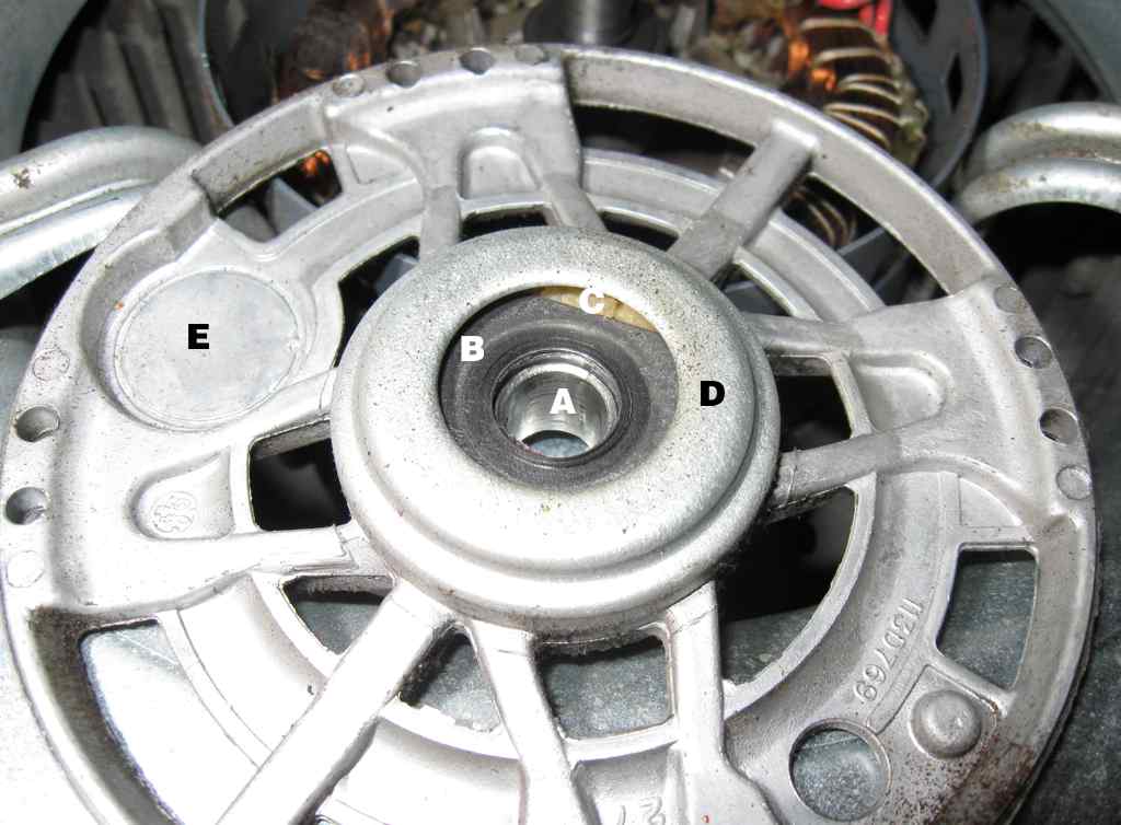
This photo shows the inner side of the end bell that was removed to reveal the inner working of the motor. The various parts are identified.
A – The bronze sleeve bearing. This bronze is made to be porous and is saturated with lubricant.
B – Plastic thrust bearing. Not very substantial but it doesn’t need to be in this kind of motor.
C – The lubricant wadding. This wadding holds a (theoretically) lifetime supply of lube for the bearing. It fills the entire bearing housing
D – Bearing housing.
E – This is an interesting and obviously unused area with an interesting history. Not too many years ago a “Klixon” type thermal overload would be located here. It detected heat from the motor windings and also responded to current flowing through it but its reaction wasn’t very rapid. The result, more often than not, was that as the motor’s bearings wore out and the rotor dragged on the stator, the bearings locked or anything else that could stop rotation happened, the windings would burn out before the overload protection operated.
Mainly in response to the many fires caused by powered roof vents, UL developed standard 507 that governs how “unattended” fans must be protected. An unattended fan is any fan that isn’t operating in the presence of a human who can detect a malfunction. The result of 507 was that the thermal overload was moved to the actual windings as shown in this article and the old spot was abandoned.
GE probably made 37 bazillion end bells so it wasn’t cost-effective to re-make the die to remove the blank and so it remains. A legacy of sorts.
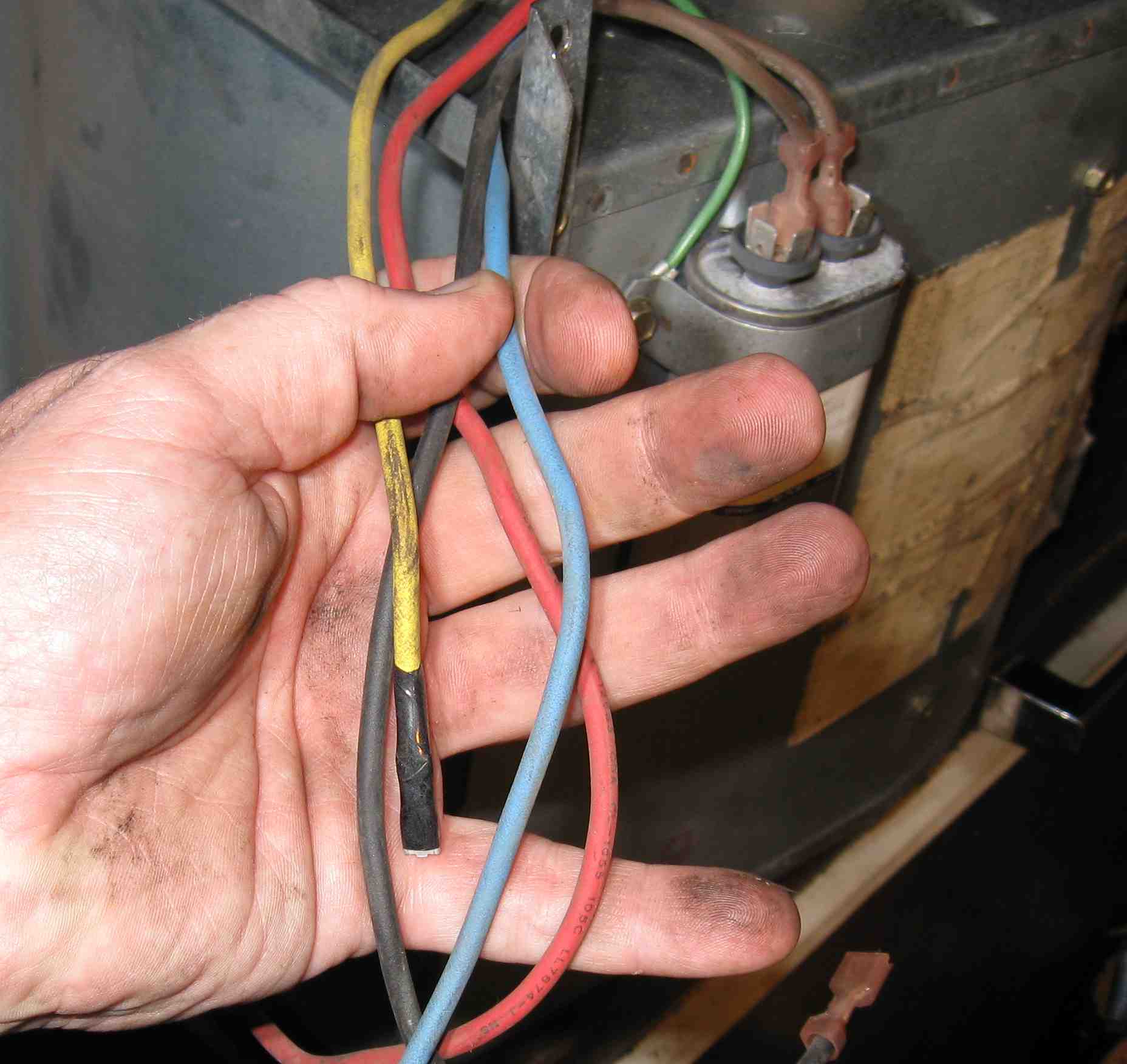
This photo shows the multi-speed connections. This is a three speed motor. As you can see, only two speeds were used and the thrird wire was stubbed off. There is an unofficial standard for color codes:
White or Brown – Common
Black – High (if present)
Yellow – Medium
Blue – Medium Low
Red – Low
Power is connected between the White or Brown wire and whichever speed is desired. In this application, Blue (medium low for AC) and Red (low for heating) were used. This is typical when a general purpose replacement motor is installed. The motor is more powerful than the OEM motor but the three speed capability let the service man select the appropriate speeds for heating and AC.
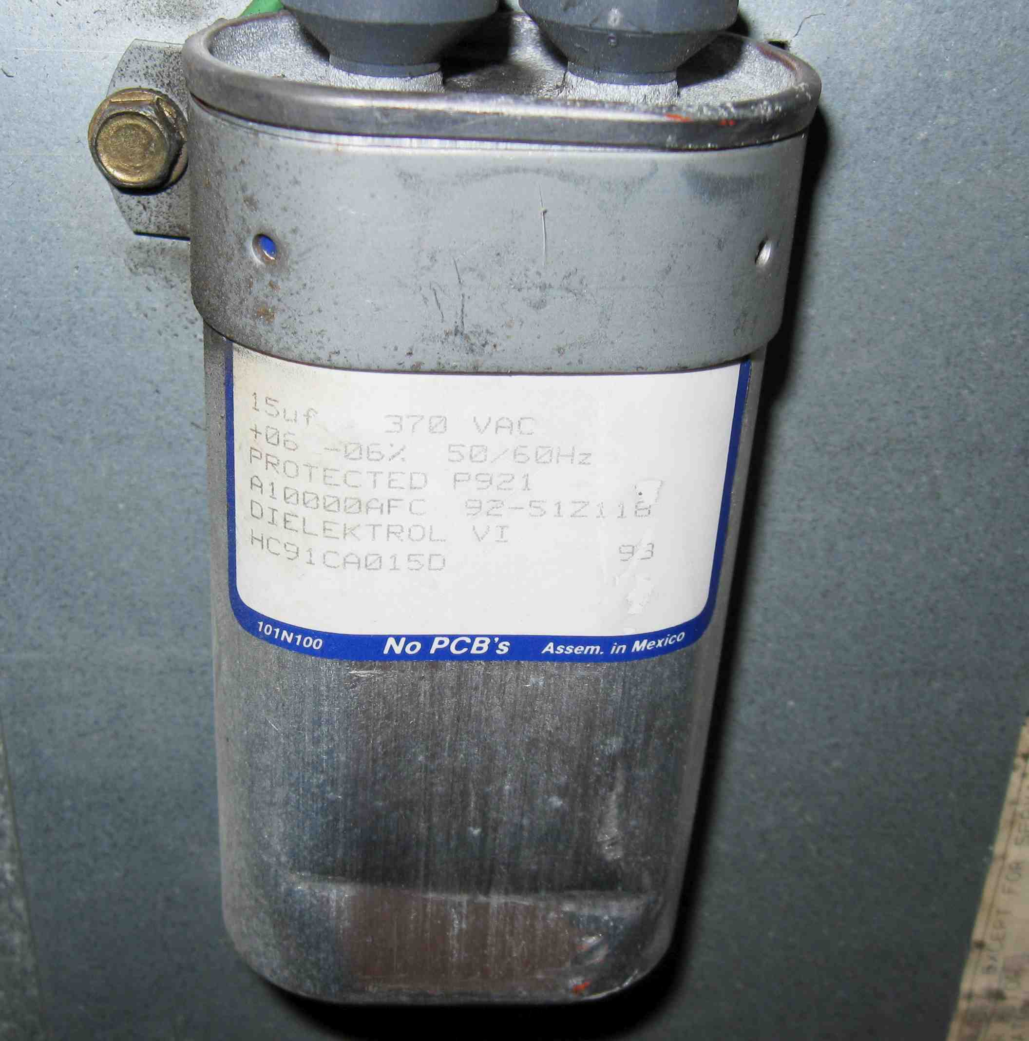
This is the “run” capacitor. It is vital to the motor’s operation. As you can see, it is rated at 15uF, 370 volts. That tells me that the motor is probably a 3/4 horsepower motor, far too large for this size fan. That’s why the service man had selected the two slowest speeds.
You’ll also note that it says “Protected”. This means that the capacitor contains internal devices that will protect it in the case of a fault.
The traditional fault would be that the cap would partially short, overheat, generate gas pressure, swell and eventually burst the can. Not good. Therefore, attached to the terminals inside the can are little links that are pulled in two if the can starts to swell. The links will also “blow” like a fuse if the cap fully shorts.
The capacitor used to be made by rolling layers of aluminum foil between layers of oiled paper and the whole assembly tightly fitted into the can. Failure was usually catastrophic.
Nowadays, there is a small plastic, usually metallized polypropylene, pre-manufactured capacitor suspended from the terminals. In this size can, it would not extend below the clamp. That’s why the dent in the bottom of the can doesn’t matter. The whole can is filled with silicone oil (usually) to cool the capacitor. The can sizes are somewhat standardized which is why they put the little plastic capacitor inside the big can. Generally, if the cap has a paper lable like this one, it is a plastic cap while if the can is engraved with the data, it’s still a paper/oil cap. Generally but not always.
Summary
This article and the thread on Usenet that spurred it graphically demonstrate why there is so much utter garbage on the net, usually presented as absolutely authoritative statements by people who don’t really have a clue. It also demonstrates why so much garbage goes unchallenged. I’ve spent over 4 hours on this article, between dismantling the blower, taking the photos, writing the script and formatting it for publication. I still must re-lace that thermal protector back in place and re-assemble the fan. Probably another 45 minutes.
I wish that I could propose a quick and simple method of separating the BS from the good stuff but I can’t. Credentials don’t matter – look at our PE buddy. High traffic sites don’t matter – I can just about pick a Wikipedia technical article at random and find major errors in seconds. About all I can recommend is to study the track record of the author of whatever info you’re considering using. I have a short list of authors whom I consider to be credible and competent but even they sometimes make mistakes. As do I.
The core problem is that there is no peer-review mechanism on the net. Like they say about the jury system, peer review sucks but it beats everything else. Google Answers tried and it worked but apparently it didn’t make them enough money so they discontinued it. Sad.
The other problem is that authorative journals and papers are buried behind “scientific societies” (really publishing companies) that charge extortionist rates for access. While I can stroll into any university engineering depository library and look at any paper ever published by, say, the SAE, I’d have to pay as much as $50 to view the same paper online and then it’s copy-protected so that it can only be printed once.
For things that really matter (read: paid client work product) I find myself still doing what I had hoped the Internet would end, trucking up to UofTN in Knoxville to use their engineering library. A sad waste of time and resources. And until someone bequeaths me a grant, I’m simply not going to spend that kind of money out of pocket to support free internet articles.
Oh well.
John
Posted by neonjohn on October 1st, 2008 under Cool Stuff, Energy, HVAC, Misc, Philosophy
October 1st, 2008 at 9:19 pm
Nice work, John. I knew that very small squirrel cage motor fans could be speed controlled; I have a 10″ Kenmore fan right here now that has a sliding contact resistor for speed control. I was not aware that furnace blower motors could. I was also not aware that the motors would overload if ran without back pressure until it happened to me! I believe in learning by experience.
October 13th, 2008 at 11:07 am
Good Job John,
I too have had “fun” with some of these sites… A good deal of the instruction on the web, should really be call “destruction”… :>)
I’ve gotten into it with people tell others how to solder and desolder SMD devices, people using high gauge wire to hookup low current electronics (man yur not arc welding here) and a interesting delete and redact session on wikipedia regarding CFL lights, power factor, and that CFL lighting instruments are actually not even close to being a good and green replacement to incandescent light fixtures… oh don’t get me started… ;>)
Keep the faith brother!
Dan
January 3rd, 2009 at 2:30 pm
Glad to see your still the same old “Givem Hell” John we all know and love. Drop me a email some time and let me know how your doing…
GM
January 17th, 2011 at 3:36 pm
Great article. Thank you for taking the time to do it and to make it available to the public. You do a great job with the photography too
BD
October 18th, 2011 at 10:59 am
How would you replace the sleeve bearing. Thanks
October 18th, 2011 at 7:06 pm
Hi Rudy,
The sad fact is that in most cases you can’t replace the bearing because no one stocks the replacement bearings anymore. Off-shore manufactured motors are so cheap that even if it only took 30 minutes to change the bearing, it would still be cheaper to scrap the motor and install a new one. Oh well.
At the shop where I moonlight some, they quit replacing bearings some 20 years ago. However I think there may be some old stock laying around. It’s like that in many shops. So just in case you can find the bearing, here’s how to change it.
1. Remove the case bolts and open up the motor.
2. Examine the shaft where the bearing contacts the shaft. If it is worn there then the motor is irreparable.
3. On the end-bell you’ll find another little housing, usually on the outside but sometimes not. It is held in place with 4 rivets. That’s where the bearing and oil retaining felt is.
4. Drill out the rivets or brads and open the housing.
5. You’ll see the bearing sitting there on some steel fingers that hold it in place while letting it rotate a little.
6. Replace the old with the new.
7. Saturate the felt with a good light machine oil such as 3-in-1 oil.
8. Put the housing back in place and either rivet or screw it in place.
9. Put the motor back together. You’re done.
John
October 23rd, 2011 at 6:11 pm
Another great article. I looked up your name on the suggestion of someone on the subject of generator backfeed and the “poor linemen” and I uncovered a mess of information and this site. Glad I did.
December 8th, 2011 at 8:49 pm
“Daestrom” is a well known troll who has been polluting engineering forums for as long as I’ve haunted the usenet. Arguing with that sort is a fool’s errand, they’re best ignored.