Los Medanos Energy Center, Pittsburg, California
June 18, 2008 at 2:15 am | Posted in Power Plant | 1 CommentOwned and operated by Calpine Corp.
Merchant plant construction has preoccupied the power industry for the past few years. At first glance, the Los Medanos Energy Center seems to fit that profile. Look a little closer, however, and you find a true combined-cycle cogeneration plant supplying power to the California grid and power and steam to an industrial customer. Los Medanos goes beyond just meeting the strictest of California’s environmental standards. Working in concert with a local water district, the plant treats and reuses its tertiary water for cooling and makeup, relieving the stress on California’s dwindling water supplies.
By Chris German, Operations Manager,Los Medanos Energy Center
Conceived years before California’s energy crisis came to a head, Calpine Corp.’s Los Medanos Energy Center (LMEC) is the first major baseload power plant to be built in the San Francisco Bay Area in more than 30 years. Located in Pittsburg, the project can produce up to 555 MW while providing process steam to a neighboring USS-Posco Industries steelmaking facility.
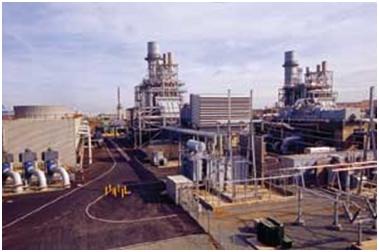
LMEC (Figure 1), one of the largest plants in Calpine’s California portfolio, sits on a greenfield site along a 115-kV transmission line about 45 miles northeast of San Francisco. The $350 million qualified facility (QF) broke ground in September 1999 and was declared commercial in August 2001. To date, the plant has performed very well (Table 1), with an average availability approaching 94% and a forced outage rate of less than 2%.
1. Los Medanos.
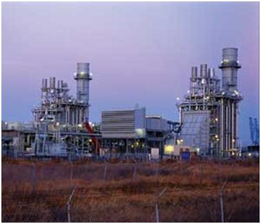
Calpine’s 555-MW Los Medanos Energy Center has a 2 x 1 configuration. Each power block has two GE 7FA+e gas turbines and a 243-MW GE D11 steam turbine. The plant’s net heat rate is 6,240 Btu/kWh.
Courtesy: Calpine Corp.
Los Medanos Energy Center operating history
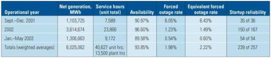
Courtesy: Calpine Corp.
The combined-cycle plant has a 2 x 1 configuration; each power block has two GE 7FA+e gas turbines that are nominally rated at 171 MW and fueled by natural gas. Also on site are two Nooter/Eriksen (St. Louis, Mo.) heat-recovery steam generators (HRSGs) and one 243-MW GE D11 steam turbine that exhausts to a Thermal Engineering condenser with 147,000 ft2 of surface area. John Zink supplied the duct burner system. A Peerless/Cormetech selective catalytic reduction (SCR) system and an Englehard CO catalyst round out the HRSG subsystems.
The plant’s tested baseload power output is 512 MW and its net heat rate is 6,240 Btu/kWh (LHV). Its peak-load power output is 554 MW at 90F.
Stringent emissions limits
Emissions limits placed on the plant (Figure 2) were 2.5 ppm for NOx, 6 ppm for CO, and 10 ppm for NH3 slip, all at 15% O2. POC (equivalent to VOC) is limited to 1.4 ppm as methane. There are also hourly, daily, and annual mass emission limits on NOx, CO, and POC, as well as daily and annual mass emission limits on particulate matter (PM) and SOx. “The limits under which we operate are among the most stringent in the nation,” says Calpine general manger Bill Ferguson.
2. Emissions limits.
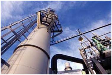
California required stringent emissions controls: 2.5 ppm for NOx and 6 ppm for CO. Post-startup testing demonstrated 2 ppm NOx and CO at 1% of the limit.
Courtesy: Calpine Corp.
Source testing in July/August 2001 showed NOx running at 2.1 ppm on Unit #1 and 1.6 ppm on Unit #2. CO was a miniscule 0.05 ppm, and NH3 was about 1% of the limit. Testing also demonstrated that NOx remained below the 2.5 ppm (1-hr) limit during transient loading (109 MW to 164 MW to 105 MW), and that NOx and NH3 slip below their limits down to 60% load.
The plant site has a unique arrangement: The steam turbine-generator sits between the gas turbines. The cooling tower is located north of gas turbine #1. LMEC’s service and maintenance buildings, water treatment plant, and other common facilities are located between the two HRSGs.
Bibb and Associates (Lenexa, Kan.) designed and specified the balance-of-plant equipment, did all the on-site field engineering, and assisted the plant’s constructor during commissioning. The constructor, managed by Calpine, was Omaha-based Kiewit Industrial Co. Construction began in September 1999, and LMEC went into commercial service in August 2001. Kiewit, which was responsible for commissioning, worked with Calpine’s Commissioning and Operations staff during this phase of the project.
Steam system details
The HP main steam system produces 1,383 psig/1,052ºF and 419,000 lb/hr per HRSG and is bypassed to the cold reheat (RH) system during startups and shutdowns. The hot reheat moves intermediate-pressure (IP) steam from the RH portion of the HRSGs to the IP/LP section of the steam turbines at 330 psig/1,049ºF and 460,000 lb/hr per HRSG. Hot RH bypasses steam to the condenser during startup and shutdown.
The process steam system provides steam for steam turbine gland steam, condenser steam air ejectors, and an average of 70,000 lb/hr (and up to 130,000 lb/hr) for export to USS-Posco Industries, the plant’s QF host (Figure 3). LMEC is also equipped with a Nebraska auxiliary boiler rated at 250,000 lbs/hr as a backup to the plant’s process steam supply to USS-Posco.
3. Steam exporter.
An average of 70,000 lbs/hr and a maximum of 130,000 lbs/hr of steam is exported to the plant’s QF host, a steelmaking facility about a mile away.
Courtesy: Calpine Corp.
Water recycling
The plant’s cooling tower water and demineralized boiler makeup water come from a tertiary “Title 22” water treatment plant. California’s Title 22 sets bacteriological water quality standards for recycled water based on how the water is to be reused. To take advantage of the availability of this reclaimed water, a water treatment plant was built by Calpine to treat the effluent from the Delta Diablo Sanitation District in Antioch, Calif., to Title 22 standards.
“LMEC and a neighboring Calpine facility receive up to 12 million gallons per day (MGD) of tertiary treated wastewater,” explains Ferguson. “We view this as a win-win arrangement in which both Calpine and the environment benefit. Wastewater that was an environmental liability for the water district has become a valuable commodity essential to the production of power.”
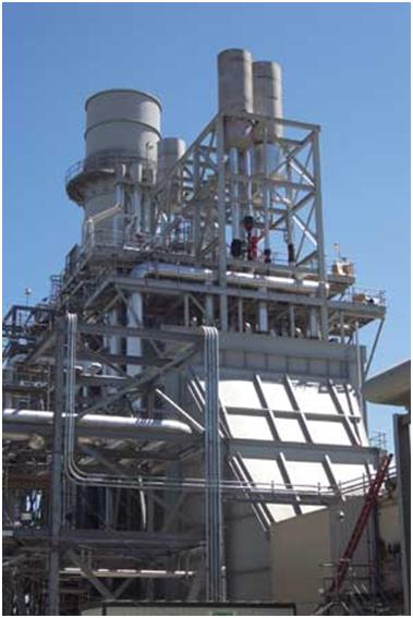
The reclaimed water for LMEC (Figure 4) is pumped 3 miles underground to a 600,000-gallon tank on the plant site. From the tank, the water is pumped both to the cooling tower and to the water treatment plant. The cooling tower, from GEA Power Cooling Systems (San Diego, Calif.) is an eight-cell, induced-draft, counter-flow unit with a nominal makeup rate of 3 MGD.
4. Water reclamation.
Los Medanos uses up to 5 million gallons per day of reclaimed (tertiary) wastewater. It is pumped three miles to the plant from the Delta Diablo Sanitation District in Antioch.
Courtesy: Calpine Corp.
The water treatment plant, whose makeup rate is about 1 MGD, consists of multimedia filters, an ultrafiltration system, carbon filters, 1-micron cartridge filters, reverse osmosis trains, a decarbonator, and ion exchange demineralizer systems. The 300 gpm of demineralized water it produces is stored in a 250,000-gallon tank for use as boiler makeup and in a 65,000-gallon tank for use in gas turbine evaporative cooling.
The electrical side
At LMEC, each turbine-generator is connected to the switchyard through a generator step-up (GSU) transformer. The three generators are synchronized to the 115-kV grid of the local utility through circuit breakers on the GSU high sides. Two auxiliary transformers (115 kV/4,160V) provide power to the plant electrical system.
The plant is connected to the local utility grid via a pair of redundant, 1.5-mile-long underground 115-kV transmission lines that terminate at Pacific Gas and Electric Co.’s Pittsburg Substation. Another pair of 115-kV underground transmission lines supply up to 70 MW to the USS-Posco facility about 1 mile away.
The plant’s switchyard has two redundant main buses and 17 SF6 gas circuit breakers with disconnect switches that serve the three GSU transformers, the two auxiliary transformers, the two utility transmission lines, the two QF host transmission lines, and two future QF host transmission lines. A 600-kW diesel engine-generator is on hand to provide emergency power to the plant’s critical loads.
LMEC’s distributed control system is an ABB-Bailey Infi-90 running Conductor VMS. It controls all balance-of-plant and equipment coordination functions.
1 Comment »
RSS feed for comments on this post. TrackBack URI
Leave a comment
Blog at WordPress.com.
Entries and comments feeds.

Check out the funniest You Tube Movies you have ever seen at http://buttonholesyoutube.blogspot.com/2010/03/kailash-releasable-opportune-youtube.html
Comment by YOUTUBE— April 4, 2010 #