Fort Myers Repowering Project, Fort Myers, Florida
June 16, 2008 at 12:58 am | Posted in Power Plant | 1 CommentOwned and operated by Florida Power & Light Co.
Florida Power & Light Co. (FP&L) probably has more experience in repowering combined-cycle plants than any utility in the U.S. The Fort Lauderdale plant (an incremental 600 MW), now operating for a decade, was followed by the Fort Myers project (an incremental 960 MW), which has been commercial for just over a year. The Sanford Repowering Project (an incremental 1,150 MW) is nearing completion. Fort Myers’ unique integration of two steam turbines, block dispatching of the integrated unit of 1,500 MW, and a manatee protection plan are unique in the industry.
By Bill Reichel, Plant Manager
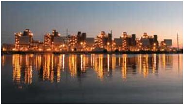
The $519 million Fort Myers repowering project (Figure 1) is unique in several ways. Filling a need for significant additional capacity in the South Florida area, it transformed 540 MW of antiquated oil-fired capacity into over 1,500 MW of state-of-the art, combined-cycle generating muscle.
1. Significant repowering.
The $519 million Fort Myers repowering added almost 1,000 MW to the 1960s-vintage oil-fired steam plants it replaced. The plant was formally commissioned on May 30, 2002. Two simple-cycle 7FAs were also installed and went commercial on June 1, 2003. The total plant capacity is now nearly 2,400 MW.
Courtesy: Florida Power & Light Co.
The plant was constructed using a unique EPCM (engineering, procurement, and construction management) services contract structure. The EPCM contractor was Florida Power & Light’s (FP&L’s) architect/engineer, which provided procurement services, labor, and material on behalf of the utility, as well as the field engineering and construction management services to oversee the installation and erection of equipment. All purchases were made via FP&L purchase orders, which were paid directly to the suppliers. Aside from engineering services, the EPCM contractor did not guarantee completion or performance of the plant; FP&L assumed the project’s schedule, completion, and performance risks. FPL Group managed the project, Kansas City–based Black & Veatch was the designer and contractor for erecting the gas turbines and the balance-of-plant and auxiliary equipment, and Foster Wheeler Inc. (Clinton, N.J.) erected the heat-recovery steam generators (HRSGs). General Electric modified and erected the steam turbines.
The “new” Fort Myers unit is a one-of-a-kind, 6 x 2 configuration in which six GE 7FA gas turbines exhaust into six Foster Wheeler 2,400-psi HRSGs, which supply steam to the two steam turbines. Because this unit has such a high capacity rating (over 1,600 MW in the winter), the design and operating procedures were set up such that the single, most severe component failure would not result in the loss of more than 910 MW.
The unit went into commercial operation on May 30, 2002, and—despite its complexities—finished its first year of operation with a stellar 2.0% forced outage rate and an availability exceeding 98%. At mid-year 2003, the forced outage rate has dropped to a even more impressive 0.50%. The plant’s NOx emissions are a state-of-the-art low 9 ppm with dry low-NOx (DLN) 2.6, and the plant’s heat rate is 6,850 Btu/kWh, which leads the FP&L fleet. The unit’s NOx emission rate is more than an order of magnitude better, and its heat rate is 3,000 Btu/kWh lower than the heat rate of the units it replaced.
System loads stress design
Fort Myers, on Florida’s southwest coast, was a low-load-growth area until recently. Satisfying demand required only a 140-MW unit (built in 1958) and a 400-MW unit built in 1969. The latter was one of seven identical oil-fired units installed by FP&L in the 1960s and 1970s. Once-through cooling water is supplied by the Calosahatchee River—an inland brackish water river that runs from Lake Okeechobee to the Gulf of Mexico.
Southwest Florida’s load growth skyrocketed over the past five years—and is now the highest in Florida—as Fort Myers became a popular retirement community. Because of the load growth and limited transmission capacity of the area, the Fort Myers plant supplies most of the region’s power, although the region remains a net importer of power.
Capacity needs forced FP&L planners to either construct a new transmission line or build a new power plant in the area. Because neither solution was appealing to the community, the next-best option was to repower the existing plant to increase its output and efficiency. A complicating factor here was Florida’s steep load curves—the plant must not only handle spring peaks but also must cycle several units off for the extremely low loads of fall, especially those at night. The summer minimum load for the plant is around 600 MW and carries virtually the entire load in southwest Florida. All 1,500 MW of capacity can be dispatched normally at 44 MW/min, but the rate can be doubled to 88 MW/min when required by the system dispatcher.
Experience: The best teacher
FP&L is no stranger to repowering aging power plants. The Fort Lauderdale repowering project was commissioned in 1993, increasing the power production from that plant by 600 MW. In addition to Fort Myers, FP&L is finishing commissioning two power blocks at the repowered Sanford power plant. The first block (Unit 5) went into service last summer and the second block (Unit 4) is currently being commissioned. When completed, Sanford will generate 2,100 MW, a big increase from its earlier 950 MW rating.
A major challenge for the construction of Fort Myers was that the 540 MW generated by the existing plant was vital to the area because of the aforementioned transmission constraints. In fact, the limited load supply to the area was a major design criterion for the entire plant—from the design of the control system to the equipment configuration to the methods of plant operation.
For example, the plant was designed so that the gas turbines could be operated in simple-cycle mode while the bottoming plant was constructed. Two stacks per GT/HRSG train were incorporated into the design, which uses a manually installed blanking plate to isolate the gas turbine from the steam generator (Figure 2). The construction was sequenced with commissioning the six simple-cycle GE 7FA gas turbines while continuing to operate the old steam plant. With the plant operating, the HRSGs were installed with their pipe racks and electrical connections. Interconnection of the plant systems to the steam turbine systems was completed during a six-month outage during the winter of 2001/2002. The GTs were kept running in simple-cycle mode until HRSG steam blows were completed in the spring of 2002.
2. Simple-cycle mode option.
The plant can be operated in simple-cycle mode with a manually installed blanking plate isolating the gas turbine from the steam generator, although it takes 24 hours to install the plate. Construction continued on the steam side of the plant with the gas turbines running in simple-cycle mode.
Courtesy: Florida Power & Light Co.
The simple-cycle gas turbines were originally commissioned over a six-month period from late October 2000 to May 2001. Construction of the HRSGs began in June 2000 and ended in April 2002. The plant was formally commissioned on May 30, 2002. Two simple-cycle 7FAs were also installed and went commercial on June 1, 2003, joining twelve 50-MW GE 7B gas turbines installed in 1972 for peaking. The total plant capacity is nearly 2,400 MW.
Operating challenges
One of the major challenges to construction of the plant was to operate the old oil-fired units while the new combined-cycle was built. In September 2001 the old steam units were shut down and overhaul of Steam Turbine (ST) #2 began. In the process, GE upgraded its output from 400 MW to 480 MW by installing new blades, the company’s “Dense Pack” technology, and new throttle/stop valves. The Dense Pack retrofit replaced the old internals of the high-pressure outer shell with more-efficient steam path components. The results, without changing steam flow, were increases in turbine efficiency, output, and throttle temperature (from 1,000F to 1,050F).
Siamese-twin turbines
Another unique aspect of the plant is the creative way the existing steam turbines were interconnected to optimize the combined-cycle plant’s efficiency. ST #1 is a Westinghouse unit configured as HP + IP + 2 x LP. The plan was to remove the HP and IP sections entirely, leaving only the double-flow LP section. ST #2 was configured so that LP extraction steam (used in the original configuration for extraction steam to feedwater heaters) is combined with the LP superheater steam from all six HRSGs and headered to the LP turbine of ST #1. The overall effect is to allow the use of all LP steam available without having to redesign or replace ST #2’s LP turbine sections. The plant calls this a 6 x 1 1/2 configuration, combined-cycle (Figure 3).
Twin turbines.
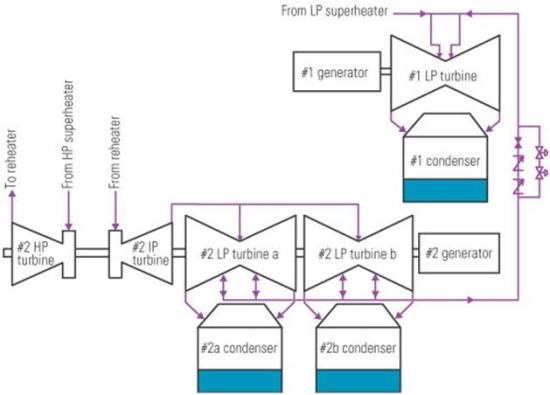
The unique combined cycle developed by FP&L engineers uses LP extraction steam from the 480-MW Steam Turbine #2 and superheated LP steam for the LP turbine of the 70-MW Steam Turbine #1. The HP and IP turbines of ST #1 were removed from service. The plant calls this a 6 x 1 ½ configuration, combined cycle.
Courtesy: Florida Power & Light Co.
The unit also has the ability to run in a more conventional 4 x 1 fashion using all the LP steam produced by the HRSGs as LP steam for ST #2. This configuration will be used only when ST #1 is down for maintenance, because it increases the unit’s heat rate.
Another unique aspect of the unit is the way it’s operated—an all-or-nothing proposition for dispatching its 1,500 MW. If the unit trips, it causes significant difficulties for the Florida electrical system, because Fort Meyers is the largest plant in the region. Previously, the largest block of load dispatched was 910 MW (the rating of the previous largest unit in the Florida electrical system). As a result, the grid’s stability rules require that no load block larger than 910 MW can ever be lost at any time, because there just isn’t enough spinning reserve available in the region. So the main criterion for plant design and operation was set: The plant cannot lose more than 910 MW in a 30-minute period.
Therefore, if the plant is operated as a single 1,500-MW power block and only 910 MW can be lost at any one time, the only choice is to continue to operate the gas turbines during a steam turbine trip. The bypass system is set up to continue operating the GT/HRSG trains at reduced efficiency for as long as it takes to return the steam turbine to service. A problem arises when the steam turbine trip is due to a loss of vacuum. When this happens, the bypass system loses its host and steam must be vented to the atmosphere. Hence, the condensate system must be capable of providing enough makeup water for all six trains for the full 30 minutes required to satisfy the system requirement.
Such a novel design required a full-scale test to prove the controls and system design (Figure 4). On a predetermined day while the plant was operating at full load, a simulated vacuum loss in ST #2 caused the turbine to trip followed by a controlled trip of ST #1. Four HRSGs automatically vented and two HRSGs bypassed to the condenser of ST #1. At the end of the period, less than 910 MW was lost to the grid, culminating in a successful test. An unplanned demonstration of the control system was experienced later when a high drum level tripped ST #2 and the plant responded just as designed and tested earlier.
4. Controls.
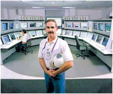
GE Mark VI controls are used for the gas turbines and retrofitted to the steam turbines. The balance-of-plant and plantwide distributed control system is an Ovation unit supplied by Emerson. Bill Reichel is Fort Myers’ plant manager.
Courtesy: Florida Power & Light Co.
Cooling water dilemma
A critical aspect of any repowering project is maintaining the plant’s existing cooling water permit. The repowering of Fort Myers succeeded in doing so, but over the course of the project the maximum temperature rise of the plant’s once-through cooling water was inexplicably reduced from 14F to 13F and a new maximum point of discharge limit was imposed. To comply with the new, lower heat-rejection limit, a helper-cooling tower designed to handle one-third of the cooling water flow was added. The helper tower runs all summer long at a cost of 4.5 MW in auxiliary load.
Manatee protection
A huge environmental issue in southwest Florida is protecting migrating manatees (see box). During the summer they migrate south, but during the winter the plant’s warm cooling water discharge attracts them. As a result, Fort Myers operates under a manatee protection plan. When the temperature of the Calosahatchee River is less than 66F, the plant must put enough heat into the discharge canal to ensure that its temperature is maitained at or above 66F. Manatee protection season is from November 1 through April 15. During this period, the plant is dispatched with these constraints to ensure that the gentle, endangered creatures are kept warm.
1 Comment »
RSS feed for comments on this post. TrackBack URI
Leave a comment
Create a free website or blog at WordPress.com.
Entries and comments feeds.

Really nice posts. I will be checking back here regularly.
Comment by Kelli Garner— October 3, 2009 #