Managing a customized Style Library in InfraWorks
Using a custom style library in InfraWorks.
When you start a new fresh model, all styles that comes with the installation of InfraWorks are available to you. You can then add a custom style, whether it is a 3D model imported from Revit, Trimble 3D Warehouse or anything InfraWorks can eat as a 3D model, or a custom made road style. But you will also notice, that the created 3D model style is only available in the InfraWorks model from where you built / created the custom style in.
To have and use it in other models you have the ability to export the custom style(s) from the current style library, so you can import it in your other models to work on.
This works fine, but this can be cumbersome if you have a lot of styles and do it all the time over and over again for new models or even existing models.
What you actually would like is to have these custom style libraries to be available to any InfraWorks model you are working on.
How, I will explain below.
How does it work.
When you start a new model in InfraWorks, all styles you are using in your model will be imported/copied from this base location:
C:\ProgramData\Autodesk\InfraWorks\Resources\LocalLibrary\Styles\
to a location where your local InfraWorks model is created and stored:
C:\Users\<<user>>\Documents\Autodesk InfraWorks Models\<<IW model name>>.files\unver\Content\Styles\
When you create a custom 3D model style in the Style Library, InfraWorks will not create the new custom style in the LocalLibrary folder location. But it creates the custom style in the user folder like mentioned above.

As the image shows, customized style libraries are stored project specific.
InfraWorks creates 1 folder and 2 files for the custom style in your user folder:
| <<imported_3D_model_name>>.style | folder |
| <<imported_3D_model_name>>.png | file |
| <<imported_3D_model_name>>.ACItem | file |
The imported 3D model with facade images are stored in the <<imported_3D_model_name>>.style folder. The 3D model is converted and named to model.sff.
The <<imported_3D_model_name>>.png file is the screenshot of the imported 3D model shown in the style library and the <<imported_3D_model_name>>.ACItem is a text file containing parameters like the used scale parameters and the location where the model is stored. Also known as URI.
This URI is of important , especially when referencing a custom library with InfraWorks.
Now copy the 3 components: the .style folder, the .png and the .ACItem files to the LocalLibrary folder structure.
Important:
When you have copyied a custom created style to the LocalLibrary folder structure, you must change this URI to the model.sff in the <<imported_3D_model_name>>.style folder.
This can be done several ways:
- Open the copied <<imported_3D_model_name>>.ACItem file from the LocalLibrary location in Notepad or any other text editor and change the path of the URI under the “EmbeddedData” section with the full path of the model.sff file found in the <<imported_3D_model_name>>.style folder.
- Or, in InfraWorks, edit the URI in the style library. But you have to do that in a newly created InfraWorks model. And when you have saved the right URI, you need to copy once more, but only the .ACItem file to the LocalLibrary folder location.
Example of a 3D model imported from Trimble 3D Warehouse in the 3D Model Style Library:
InfraWorks creates the following folder & files below the 3D Model folder of your local model:
C:\Users\<<user>>\Documents\Autodesk InfraWorks Models\<<IW model name>>.files\unver\Content\Styles\3D Model\
| <<imported_3D_model_name>>.style | folder |
| <<imported_3D_model_name>>.png | file |
| <<imported_3D_model_name>>.ACItem | file |
Now by copying this folder and files to the LocalLibrary location, and by changing the path of the URI in the <<imported_3d_model_name>>.ACItem file like I mentioned above, the custom style will be available to all newly created and existing InfraWorks models.
Note:
When you update the custom library while you work in a model, you have to re-open the model, to update the style library. Re-opening should be done by openening another model and then go back to the actual model.
When you have both InfraWorks and InfraWorks 360 on your system and you want to make use of only 1 content library, set the registry variable ContentLocalLibraryPath to the same folder path. You can find this registry variabele in the HKEY_LOCAL_MACHINE\SOFTWARE\Autodesk\InfraWorks and HKEY_LOCAL_MACHINE\SOFTWARE\Autodesk\InfraWorks 360 registry paths.
Enjoy
How to use WMS in InfraWorks
Now that you know how to grab or download an image from a WMS server, and how to create a World File for it, the next step is to create an XML file which can be used as a Raster in InfraWorks.
This XML file will be used as a connection to retrieve an image from a WMS server. As soon as it completes the download of the image from the WMS server it will store this in the InfraWorks (SQLite) model. Now every time you reconfigure this Raster feature in InfraWorks it will reconnect to the WMS server using this XML file.
The XML file is built of a format known as GDAL WMS. The complete format is explained over here. We are going to use the same parameters as we have used in our example in our post How to grab aerial image maps from WMS server.
To read the URL easier and to compare it with the GDAL WMS format the parameters are shown below in several rules.
http://geodata1.nationaalgeoregister.nl/luchtfoto/wms?
version=1.1.1
&request=GetMap
&layers=luchtfoto
&SRS=EPSG%3A28992
&BBOX=208670.623,375465.3687,209670.623,375965.3687
&FORMAT=image%2Fjpeg
&WIDTH=2000
&HEIGHT=1000
&STYLES=
Note that the BBOX coordinates are setup from LowerLeftXY to UpperRightXY.
The above URL translated into a GDAL WMS XML format looks like this:
<GDAL_WMS>
<Service name=”WMS”>
<Version>1.1.1</Version>
<ServerUrl>http://geodata1.nationaalgeoregister.nl/luchtfoto/wms?</ServerUrl>
<SRS>EPSG:28992</SRS>
<ImageFormat>image/png</ImageFormat>
<Layers>luchtfoto</Layers>
<Styles></Styles>
</Service>
<DataWindow>
<UpperLeftX>208670.623</UpperLeftX>
<UpperLeftY>375965.3687</UpperLeftY>
<LowerRightX>209670.623</LowerRightX>
<LowerRightY>375465.3687</LowerRightY>
<SizeX>2000</SizeX>
<SizeY>1000</SizeY>
</DataWindow>
<Projection>EPSG:28992</Projection>
<BandsCount>3</BandsCount>
</GDAL_WMS>
Note that the DataWindow coordinates are setup from UpperLeftXY to LowerRightXY. A common mistake is when the BBOX coordinates are used as the DataWindow coordinates, which will surely result in an error when configuring the XML in InfraWorks.
Click here to download the wms.xml file.
Now use this XML file as a Raster feature in Infraworks and configure it. The aerial image map will be retrieved from the WMS server right into InfraWorks.

Happy Web Map Service! 🙂
How to create a World File
In continuing effort of my last blog post, I will explain how you can create a simple world file to use with an image which is not georeferenced to use with AutoCAD MAP, Civil 3D and/or InfraWorks.
In my previous blog post “How to grab aerial images from WMS server” you have made a rectangle (or square) as the boundary to your project of where you want to download an aerial image from a WMS server.
Now I will use the same example to write down the coordinates of the upper left corner of that rectangle (or square). Now use the half of the value of the factor I have calculated back then (which is in fact the ground resolution of that particular image) and add this value to the X ordinate, and subtract the same value from the Y ordinate. The result will be used as the coordinates for the World File which in return will be used as the insertion point of the aerial image map.
Now create a text file with the following content (6 rules):
[calculated factor]
0.0000000
0.0000000
-[calculated factor]
X (value = UpperLeft X ordinate plus half the value of the calculated factor)
Y (value = UpperLeft Y ordinate minus half the value of the calculated factor)
If I use the same URL example from my previous blog,
the content of my World File will be as follows:
0.500
0.000
0.000
-0.500
208670.873
375965.1187
Save the file with the same name as the image you have downloaded from the WMS server but with the file extension built as follows:
If your image has the jpg file extension, use jgw as the file extension for the World File. You can name any bitmap file extension by omitting the 2nd (or middle) character and by shifting the 3rd (or last) character to the left and finally by adding the ‘w’ character to the end. So ecw would become eww and png would become pgw, etc.
You can also download the file here.
Now you can use both files, the downloaded aerial image with the self made World File in AutoCAD Map / Civil 3D or InfraWorks. You may even use these files in vanilla AutoCAD if you like, by using this free available tool: GeoRefInsert from the Autodesk Exchange Apps store.
In my next blog post I will explain how you can successfully use a GDAL WMS XML file to use with InfraWorks.
Happy georeferencing! 😃
How to grab aerial maps from WMS server
With AutoCAD Map 3D or AutoCAD Civil 3D (planning and Analysis workspace) you can connect to a WMS data server via the MAPCONNECT command. Once connected you can select a Layer or layers from the available presented list of layers, choose the coordinate system corresponding to the one you have set in your drawing and add the data to your drawing. If everything runs well your window screen will be filled with all the layer data from the selected WMS server. Aerial Imagery maps can be served this way. Once you’ve connected and add aerial images to your map, your window will fill with aerial images. But you will not recoginize much detail. But by zooming in, much more detail will become available until a maximum value is reached. This maximum value is explained as ground resolution and stands for the image content expressed in a distance in units per pixel image. For example: 0.5m/pixel or 50cm per pixel. The smaller the units expressed in cm or m (or inches/feet) the better the quality of the image.
However, you can not grab the image directly in AutoCAD Map 3D or Civil 3D to use as a standalone or as an attached image. For this you could make a printscreen of your AutoCAD Window. But the resolution is as ‘good’ as your resolution of your screen. You could also use the re-sample function from the MapWorkspace to download the active screen to a temporary folder on disk. In both cases the retrieved imagery is not georeferenced and therefor hard to insert at the right coordinates back into the drawing.
Another and much better way is, to use the EXPORTMAPTODWG function, which will allow you to create a new DWG with the image attached to that DWG. But only the image of what you visual have zoomed into at that moment will be captured, created and attached. This way you have the retrieved image positioned at the right coordinates in the drawing. But the image resolution is as good as the resolution from screen.
There is an alternative way to do both: get a better image resolution and have the image georeferenced. How to grab an aerial image map from a WMS server, right after the jump. Grabbing an aerial image map from a WMS server can be done via a web browser by using a typical URL with special parameters which the WMS server understands for retrieving the requested data from the server. But before you built this URL, you need to know which required parameters the wms server is using. This can be done by using the GetCapabilities request first. An example is given below:
http://geodata1.nationaalgeoregister.nl/luchtfoto/wms?request=GetCapabilities
This will return an XML file which can be opened in any text or XML editor.
In the next section I will explain which of the parameters can be used to built the GetMap request URL. The GetMap request URL can have or should contain the following parameters:
- Built the URL starting with the same WMS url you have used with the MAPCONNECT function in Map 3D or Civil 3D. Mostly it ends with a ? mark or & mark. What follows next does not have to be in a certain order. I.e http://geodata1.nationaalgeoregister.nl/luchtfoto/wms?
- Place the version=x.x.x phrase into the to be built URL. To know which version the wms server is using, request it by using the GetCapabilities first. I.e http://geodata1.nationaalgeoregister.nl/luchtfoto/wms?version=1.1.1
- Place the REQUEST=GetMap phrase into the to be build URL like in the example below. Add the & character in front of the phrase. I.e. http://geodata1.nationaalgeoregister.nl/luchtfoto/wms?version=1.1.1&request=GetMap
- Place the LAYERS=layer name<,layer name> phrase. Add the & character in front of it. Use the same layer name(s) you have used in Map 3D/Civil 3D when connecting and adding the layer(s) to your Map. The right layer name(s) can be different than the display name(s) Map/Civil 3D will show you. If you want the exact layer name(s), make use of the GetCapabilities request in an Internet browser before you continue. From that response you can filter out the right layer name(s). I.e. http://geodata1.nationaalgeoregister.nl/luchtfoto/wms?version=1.1.1&request=GetMap&layers=luchtfoto
- Determine the geographical or Projected coordinate system expressed as a EPSG code and place it into the URL as follows: SRS=EPSG:code or CRS=EPSG:code. Use CRS for 1.3 versions only. Replace the : character in the url with %3A. The required epsg code can also be found by using the GetCapabilities request first. I.e. http://geodata1.nationaalgeoregister.nl/luchtfoto/wms?version=1.1.1&request=GetMap&layers=luchtfoto&SRS=EPSG%3A28992
- Place the BBOX=LowerLeftX,LowerLeftY,UpperRightX,UpperRightY in the URL. And add the & character at the start. Define a window in Map3D/Cvil3D and determine the lower left and upper right coordinates. Draw a rectangle for example and write down the upper left and lower right coordinates. These coordinates will be used in the boundingbox (BBOX) part of the URL. I.e. http://geodata1.nationaalgeoregister.nl/luchtfoto/wms?version=1.1.1&request=GetMap&layers=luchtfoto&SRS=EPSG%3A28992&BBOX=208670.623,375465.3687,209670.623,375965.3687
- Place the FORMAT=image/jpeg phrase in the URL but replace the / with %2F so it will show image%2Fjpeg in the URL. Add the & character at the end. I.e. http://geodata1.nationaalgeoregister.nl/luchtfoto/wms?version=1.1.1&request=GetMap&layers=luchtfoto&SRS=EPSG%3A28992&BBOX=208670.623,375465.3687,209670.623,375965.3687&FORMAT=image%2Fjpeg
- Use the maximum allowed WIDTH and HEIGHT of the image grabbed from the WMS server. This could be different for every WMS server. Most of the times I found, sometimes by trial and error or sometimes by using the GetCapabilities request, the value of 2000 or 2048.
- Now here comes the trick: calculate the width and height values of your rectangle to the maximum WIDTH/HEIGHT so the width and height are in relation to each other. For instance: your largest side (width) of the rectangle is 1000m. Then your WIDTH value will be the maximum WIDTH of 2000. It needs a scale factor of 0.5 to get the 2000 into 1000m. Your shortest side (height) is 500m. Then your HEIGHT will be 1000 by using the same scale factor of 0.5. If you have drawn a rectangle with equal width and height, a square, you can use the same value for the maximum WIDTH/HEIGHT of the WMS server. This scale factor is also important for creating a World File later. I.e. http://geodata1.nationaalgeoregister.nl/luchtfoto/wms?version=1.1.1&request=GetMap&layers=luchtfoto&SRS=EPSG%3A28992&BBOX=208670.623,375465.3687,209670.623,375965.3687&FORMAT=image%2Fjpeg&WIDTH=2000&HEIGHT=1000
So the complete URL example of a WMS server GetMap request could look like this: http://geodata1.nationaalgeoregister.nl/luchtfoto/wms?LAYERS=luchtfoto&FORMAT=image%2Fjpeg&VERSION=1.1.1&REQUEST=GetMap&STYLES=&SRS=EPSG%3A28992&BBOX=208670.623,375465.3687,209670.623,375965.3687&WIDTH=2000&HEIGHT=1000
Applying the GetMap request URL into any webbrowser will result in showing the image within the given boundingbox. The below image is just for reference and will not have the same resolution as the image when you click the above URL.  Rightclick the image applied from the above URL and save it to your harddrive or network share. You now have the image ready to be used in AutoCAD. But you are not there yet. This image example isn’t georeferenced. If the WMS server supports GeoTiff images, only then the saved image is geo referenced.
In my next post I will explain how to create a World File for non GeoTiff images like above example. Without using an application or add-on which can create World Files from images like Raster Design does.
Stay tuned.
Add an offset boundary line to a corridor
I got a question of one of my students of how to create a land acquisition boundary line from the outer limits of a corridor at an offset of 0.50m outside the daylight cut or fill feature lines.
My first reaction was to do it by extracting a feature line from the corridor and then stepped offset it with a distance of 0.50m and a grade of 0.00% to the outside of the corridor, assign elvations from surface, assign it a style and you’re done. But then you have to recreate it over and over again every time when the corridor is rebuild.
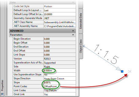
If you want to automate this, the solution lies within the corridor itself. In fact, within the assembly it’s built from. So this is how I solved it: add a LinkWidthAndSlope subassembly placed at the end of any daylight or LinkSlopeToSurface subassembly, add 0.50m to the Width value and 0.00% to the Slope value.
Last but not the least: Omit the link, so it will not be used by the corridor for creating corridor surfaces. And you should also name the P2 point code to a more appropriate name like: Boundary or OffsetPoint, and incorporate this code to your code set style where you assign it a feature line style.
Now every time you recreate the corridor, the boundary is updated.
But this is not quite what I was looking for. It works great for plan view purposes only. But if I want to have information of the existing ground surface for stake-out purposes for example, then I want to have the boundary line to follow the exisiting ground conditions. So I added an extra subassembly to determine the exact daylight point at the applied offset. And I added the LinkSlopeToSurface subassembly with a cut or fill slope of 99999% which is near to vertical placed at the end of the outer LinkWidthAndSlope subassembly.

Don’t forget to Omit the link. This will show a total different layout than when it’s not omitted.

Rebuild the corridor and you’ll see like in below picture in Plan view and in Section view how the boundary line looks like.

In cross section view I added a guardrail markerpoint to see it more clearly of where the boundary line will follow the exisiting ground.

So by going horizontal first and then going vertical next answered the question.
If there’s a better way to do this, please respond. I’m open to any suggestion.
Enjoy!
Note: There is a LinkOffsetToSurface subassembly, but that one offsets only from the Assembly Baseline and not from the attached point of the subassembly itself. I’ve tried to use it instead of the above solution by using (turning on) the Use option with the assembly which should transfer the value of another subassembly value. I’ve tried to copy/use the LinkWidthAndSlope.Offset End value but that one failed.
AutoCAD WS supports Civil 3D drawings
Great news. At least for the mobile AutoCAD WS users.
AutoCAD WS, for the iPad at least, now supports Civil 3D drawings, and it works great.
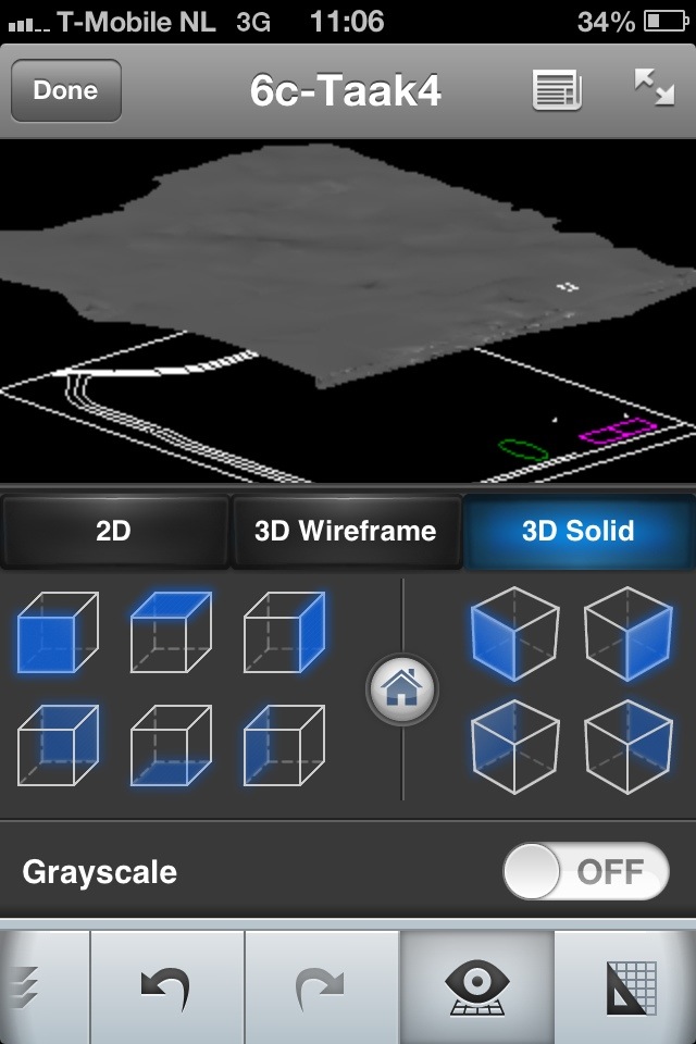
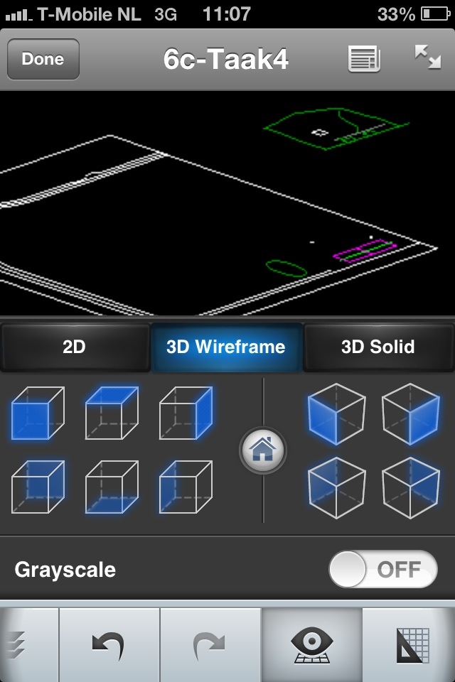
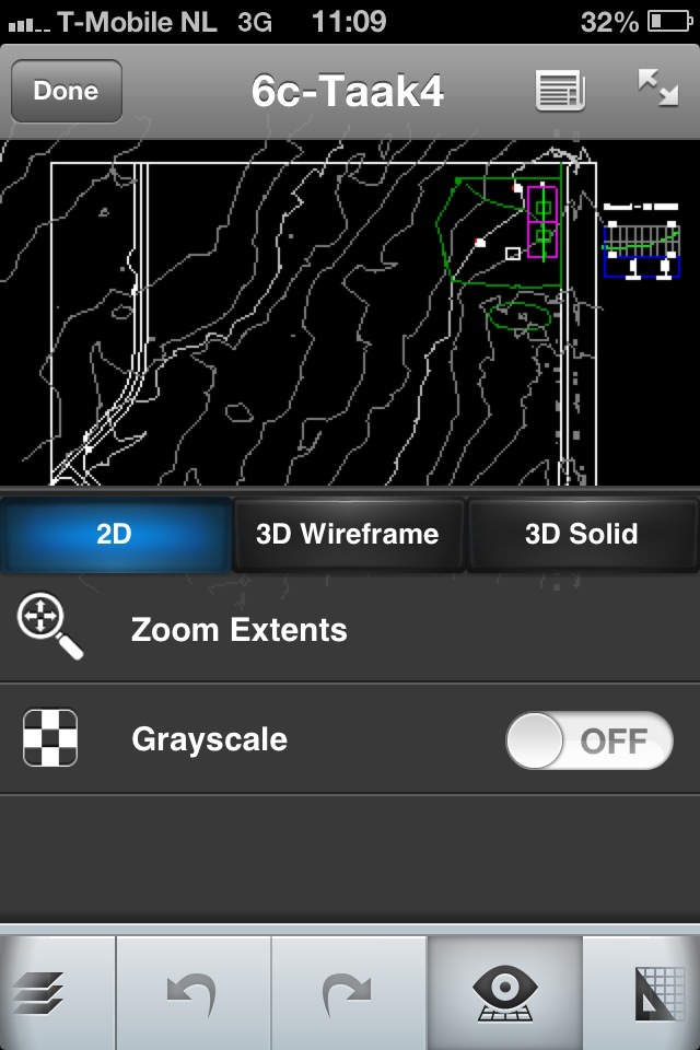
When you open an AutoCAD Civil 3D drawing in the AutoCAD WS app you will see the drawing in one of the 3 available Views: 2D, 3D Wireframe and 3D Solid. You can easily switch to either one of those Views.
If you have a Surface in the drawing, the 3D Solid View will show you the solids of the triangulation of the surface. Just like you would see when you make use of the Object Viewer by selecting the Surface within AutoCAD Civil 3D.
Switching to 2D View will show you the drawing in Plan View.
Switching to 3D Wireframe View will show you the drawing in 3D View showing Civil 3D objects like Feature Lines and probably more objects as I first have to test this more.
See: AutoCAD WS
See also below images made from my iPhone:
Adoption of a Digital Terrain Model (DTM) with Microstation V8i (SELECTseries 3)
This video will show you how you can import a LandXML file containing a DTM surface into vanilla Microstation V8i (SELECTseries 3).
WHAT?
Yeah, I know. It has nothing to do with AutoCAD Civil 3D itself, besides that Civil 3D can export (and of course also import) LandXML files. So when you have a contractor or client or other project team using Microstation V8i (SELECTseries 3) you could share your Civil 3D TIN surface through LandXML export.
")
I really like this adoption of the LandXML DTM/TIN feature with Bentley’s flagship Microstation because it has all the functionality to change the style of the Surface and annotate it where needed in the drawing. You can not though change or alter the TIN surface in anyway. But in most cases you don’t need to alter the TIN surface when you are in a phase of the project when you need to create construction drawings and the existing or proposed ground surface does not change at all anymore.
I really would like to see this functionality in vanilla AutoCAD too.
Go see and check it out: Import LandXML into MicroStation V8i (SELECTsereis 3) and Annotate – Terrain Model (via Twitter: @EnvisionCAD and @Blip)
Unable to execute the tool – Fixing the Toolpalette
Here’s a quick remedy for the following error:
In AutoCAD Civil 3D 2012, when I want to insert a subassembly from the Toolpallette or Content Browser, I get this error:

I did not know what caused this error. But repairing or even re-installing the application did not solve the issue. At least for me it didn’t. I couldn’t find any solution from the Autodesk support website so I made a support request at Autodesk Subscription Tech Support. They replied: re-install the application. Well that didn’t work.
So I was delivered to the resources of the internet community. And that’s not bad as you may read right after the jump.
Out there on the web I read that it had something to do with the way you’ve made the installation, through manual installation or through network deployment. Working as a CAD application administrator I always use deployments because of the many installations we need to make. Looking further on the internet, I even found a blog page describing the same error and the solution for an AutoCAD MEP installation. Read here for their findings. Their solution was that within the User’s roaming Support\RegisteredTools folder I should have had the appropriate files in it.
So I made a manual (stand-alone) installation on another system and compared that with the network deployment. With the manual installation under the User’s roaming Support\RegisteredTools folder I found the right files in it as described before with the AutoCAD MEP installation. Where the network deployment installation did not had these files under the User’s roaming Support\RegisteredTools folder.

The location for Windows 7 or Vista is:
“C:\Users\<user account>\Roaming\App data\Autodesk\C3D 2012\enu\Support\RegisteredTools”.
So I’ve copied those files from the manual installation location to the network deployment installation location, started AutoCAD Civil 3D 2012, and there you go. Inserting subassemblies from the ToolPalette or even from the Content Browser did not gave me the “Unable to execute the tool” error anymore.
You can download these 3 .atc files here.
Preview of Queried Survey Points seems lost
New survey features are introduced with the release of AutoCAD Civil 3D 2013.
One of those new features is the Survey Query Builder. The Survey Query builder gives you the opportunity to build your survey data (point and figures) by using queries or filters. This way you can select what survey data you want before you import it into the drawing.
On the internet you can find lots of information how you can build such a survey query. The User Guide documentation of Civil 3D 2013 has also sufficient information how to do so.
Once you’ve build your query, you can preview the result in the drawing editor. And if satisfied you can save the query for later use to import your result into the drawing.

One thing I’ve noticed when I tried to Preview a points query only, is that I could not see the result (any points) in the drawing editor.
Taking a closer look, and I actually had to zoom in from great distance, you could finally see the points. That is awkward.
I could not find any documentation how to change the display style of the points in preview mode.
So to see the points in preview mode I have added a large drawing (or annotation) scale like 1:5,000 or 1:10,000 to the scale list. Set this large scale before you want to see a preview of your queried survey points and voila there are your points.
When you’re done with querying your survey data do not forget to turn your drawing scale back to an appropriate scale. If not you could end up with very big annotations or graphical representations of your points when you want to import those points into the drawing. If so, you know how to change the scale back to a more working presentation.
Note: this problem only occur with the Metric version of Civil 3D 2013.
Civil 3D book reviewed: AutoCAD Civil 3D 2013 Essentials
As a Civil 3D addict I read a lot of resources about this subject. Besides the many great resources found and available on the internet like blogs, I also read great Civil 3D books. One of those great books is AutoCAD Civil 3D 2013 Essentials written by Eric Chappell.
I have reviewed this book with Amazon. You can read it right here
The clear approach of a likely real world Civil project from start to end through the whole book is really great. Not to mention that besides Imperial units it uses Metric units too. The approach of the use of supported videos is innovative and can be downloaded via the Amazon or Wiley website but can also be watched via YouTube.
The book is targeted for starters, but even I as a Civil 3D teacher have learned better understand the automated field to finish in Survey. This is the first Civil 3D book I’ve found which clearly and extensively explains how the automated field to finish works in Survey using a point file in the PENZD text format in a likely real world project. The only thing I’ve missed in this part is the explanation of how a surface can be build by using the newly introduced survey query command. Besides that it is really a great book.
I can recommend this book to everyone who wants to learn Civil 3D by themselves or as a guidance when learning by a teacher in a class.
